
Documented cable plant
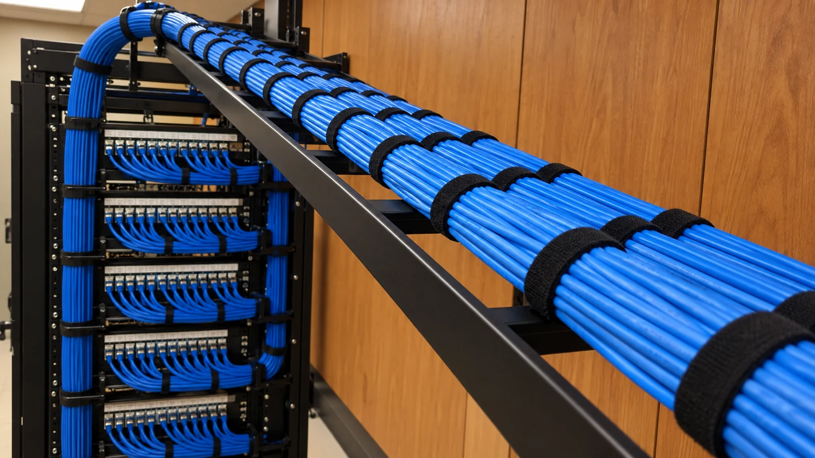
Labels, termination records, and test results make moves and fault isolation more practical.
Commercial Technology Solutions | Ocala and Marion County
Structured cabling is the passive copper infrastructure that connects work areas, cameras, wireless access points, access-control devices, and other networked endpoints to organized telecom spaces. A useful scope defines pathways, category, distance, termination, labeling, and test expectations before active equipment is selected.
The cable plant should remain understandable after ceilings close and personnel change. Drop schedules, route decisions, endpoint identifiers, patch positions, and test records turn hidden infrastructure into a serviceable asset.
Labels, termination records, and test results make moves and fault isolation more practical.
Routes are reviewed for distance, separation, access, bend, fill, and future expansion constraints.
Camera, access, AP, workstation, and building-system connections are planned around their actual placement and service needs.
FL License #EC13016138 supports factual provider identification for the low-voltage project.
Copper cabling performs best when the link category, route, termination hardware, patching, and test method are treated as one channel. A rack full of switches cannot correct an overlength run, damaged pathway, poor termination, or missing label.
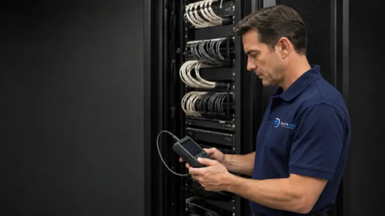
Retrofits may require careful routing around finished ceilings, tenant operations, rated assemblies, and inaccessible wall cavities.
Copper links must remain within applicable distance limits; detached or remote locations may require a telecom room, fiber, or another backbone design.
Mixed jack, patch-panel, pinout, and workmanship practices create intermittent faults that are difficult to trace.
Unlabeled cables and undocumented moves make every later change slower and risk disconnecting the wrong service.
Select the copper category based on link requirements, pathway conditions, endpoint needs, and an appropriate expansion horizon.
Provide dedicated routes for desks, cameras, access-control panels, readers, intercoms, and wireless access points.
Terminate horizontal cabling into labeled patch fields with serviceable dressing and planned rack position.
Coordinate sleeves, conduit, tray, supports, pull access, and telecom-space entry points before finishes conceal the route.
Terminate both ends consistently and test the completed link to the level required by the project scope.
Use identifiers that connect faceplates, devices, cable ends, patch panels, rooms, and test records.
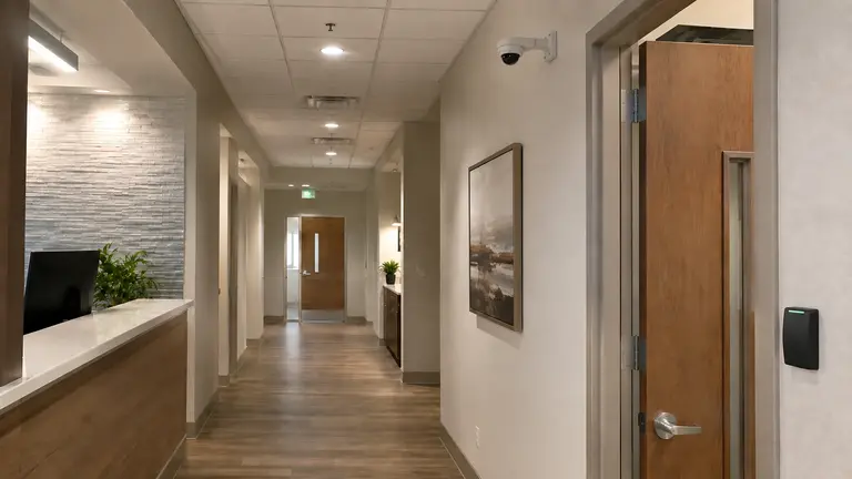
Add data and device drops without allowing cabling work to disrupt patient-facing rooms more than the approved schedule permits.
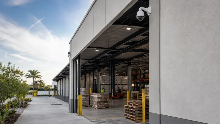
Create organized copper home runs to reachable telecom locations rather than stretching channels beyond practical limits.

Coordinate furniture, ceiling, wall, and telecom-room decisions before outlets and pathways are fixed.

Route reader, request-to-exit, door-position, power, and network-related cabling according to the access-control design, while preserving the distinction between cable work and system programming.
Walk the proposed route, identify penetrations and supports, and confirm the cable can be installed and serviced.
Match copper category and channel design to required applications, installed conditions, and realistic run lengths.
Define outlet, patch-panel, rack, faceplate, and identifier conventions before field work begins.
State the required test method, deliverable format, failed-link correction process, and as-built record expectations.
A camera drop can carry data and PoE, an AP drop can support wireless coverage, and access-control cabling can reach door devices. Switching, Wi-Fi design, camera configuration, and credential administration remain separate technical scopes.
Office renovations need clean coordination with furniture and finishes, while warehouses and managed properties may require long routes, multiple telecom areas, and staged work around occupied operations. Large sites should identify where copper stops being practical before the route is committed.
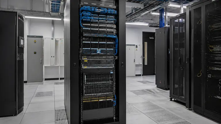
Connect the passive cable plant to switches, PoE, uplinks, segmentation, and active connectivity.
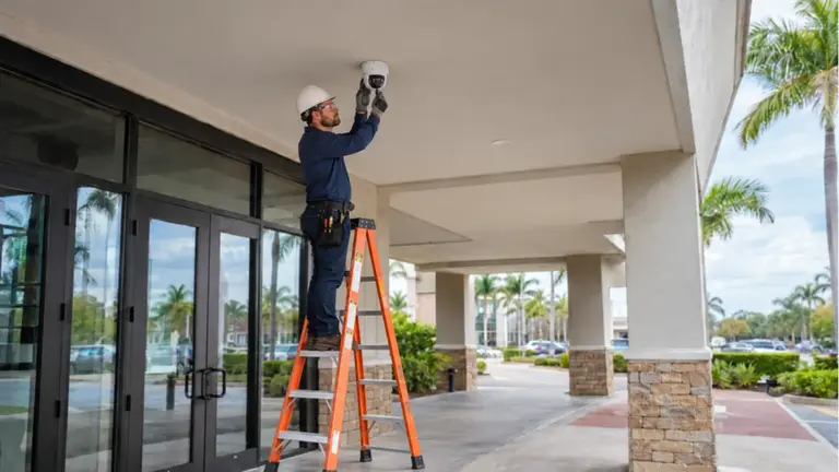
Use the documented pathways and drops to support planned camera scenes and recording.

Coordinate door-device cabling with the controlled-opening hardware and credential workflow.
Commercial offices, healthcare suites, warehouses, schools, managed properties, and buildouts use different outlet densities, access conditions, pathway constraints, and work sequences.
Build a drop schedule tied to plans, device locations, and future capacity.
Confirm physical access, distances, supports, penetrations, and rack destinations.
Place, dress, terminate, and label each run to the approved schedule.
Correct failed links and deliver identifiers, results, and as-built changes.
Ocala Security Cameras by Data Pro Communications is operated by Data Pro Communications for the Ocala Branch. Contact information: 603 E Fort King St, Ocala, FL 34471; (352) 517-4404; info@dataprocommunications.com. FL License #EC13016138.
Questions and answers
A complete scope can include pathway coordination, Cat6 or Cat6A cable, device and work-area drops, patch panels, jacks, faceplates, supports, termination, labeling, testing, and as-built records.
The choice depends on the application, link length, pathway capacity, bundle conditions, equipment roadmap, installation environment, and project standard. Cat6A is useful in some designs but is not automatically required for every drop.
Copper between buildings can introduce distance, grounding, surge, and electrical-potential concerns. Fiber or an appropriate outdoor link is often evaluated for detached structures, but the final choice depends on the pathway and design.
The required result may range from wire-map verification to certification against a specified category. The project should define the test standard, instrument output, identifier format, and correction expectations before installation.
Identifiers should connect the endpoint, room or door, cable, patch-panel position, and telecom location. The convention must remain readable to the teams maintaining the systems later.
Only after confirming rack space, patch-panel capacity, grounding/bonding responsibilities, cable management, power, cooling, switch ports, and access. A crowded rack can turn a small cabling addition into a broader infrastructure correction.
Damaged cable, excessive bend or tension, poor termination, loose patching, unsuitable connectors, water exposure, electromagnetic conditions, and active equipment faults can all contribute. Testing should isolate the passive link from the connected devices.
Coordinate outlet locations, wall types, ceiling access, sleeves, conduit, tray, telecom rooms, firestopping responsibility, and inspection sequence before finishes close the routes.
No. The cable plant delivers tested passive links. Switch selection, PoE allocation, VLANs, addressing, and configuration belong to Network Infrastructure or the responsible IT scope.
Provide plans if available, endpoint counts, device types, room and rack access, ceiling and wall conditions, existing labels or test records, construction schedule, and areas where work hours are restricted.
Request a pathway and drop review for a buildout, retrofit, camera expansion, access-control project, or network refresh.