
Capacity before cutover
Port, PoE, and uplink demand are compared with available equipment before new endpoints are connected.
Commercial Technology Solutions | Ocala and Marion County
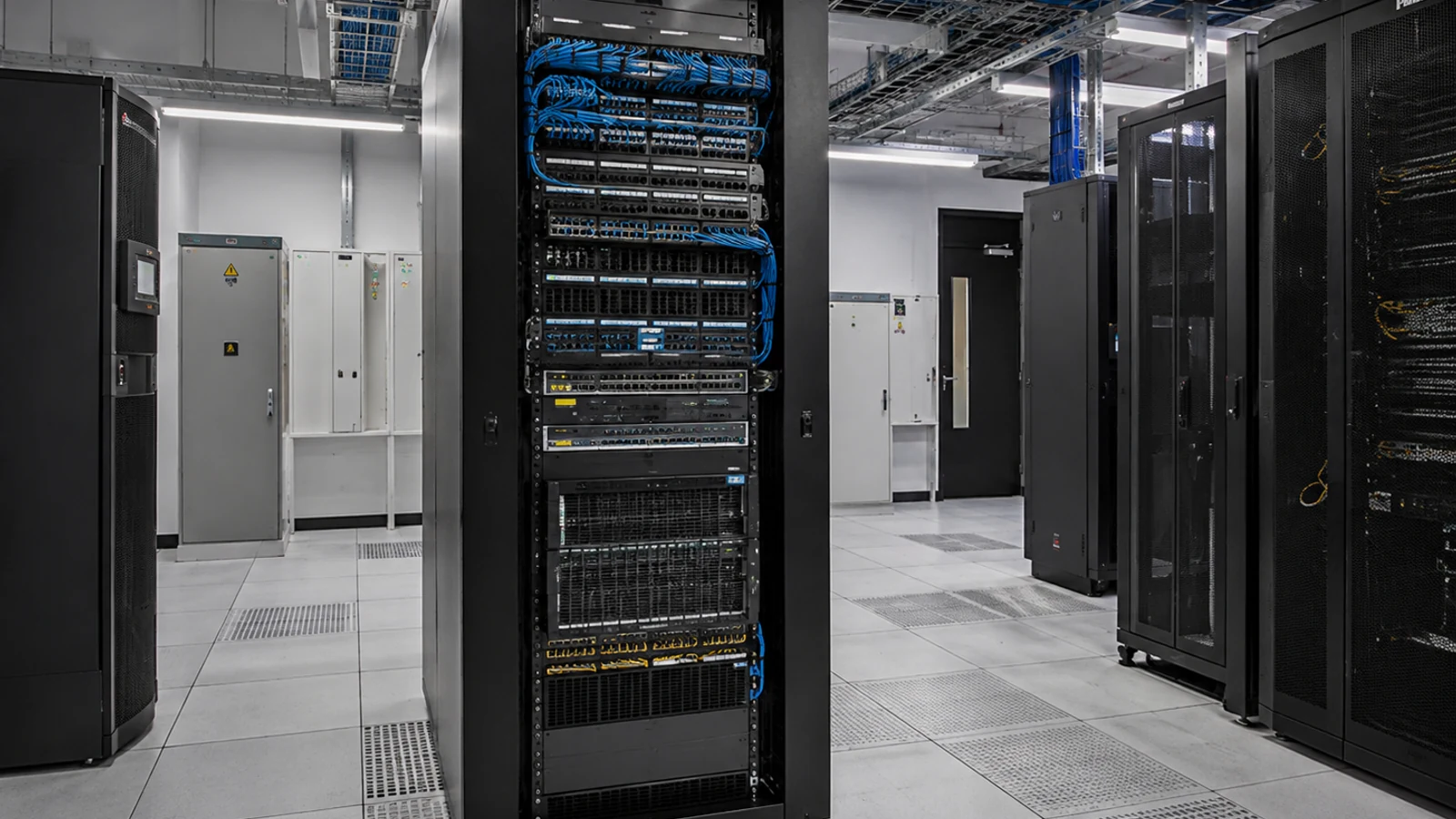
Network infrastructure is the active connectivity layer that carries business, camera, access-control, wireless, and building-system traffic. The design must account for switch ports, PoE load, uplink capacity, rack organization, logical separation, equipment ownership, and the route between telecom locations.
Active connectivity decisions should be visible before new devices consume ports and power. A topology that names switches, uplinks, device groups, owners, and failure points is easier to expand than an accumulation of unrecorded changes.
Port, PoE, and uplink demand are compared with available equipment before new endpoints are connected.
IT approvals, credentials, addressing, firewall rules, and managed services remain assigned to the responsible party.
MDF and IDF conditions are reviewed for space, power, cooling, patching, uplinks, and service access.
FL License #EC13016138 identifies the branch provider without implying a managed-IT certification.
A network for cameras and access control is more than an available Ethernet jack. Device counts, traffic patterns, PoE classes, uplinks, multicast or broadcast behavior, management platforms, remote access, and failure impact all affect the switching plan.
A switch can have open ports yet lack the power budget needed for cameras, wireless access points, readers, or intercom stations.
Edge ports may operate normally while oversubscribed uplinks constrain video, backups, or traffic between buildings.
VLANs and policies require responsible IT approval; creating labels without routing, firewall, and management decisions does not create isolation.
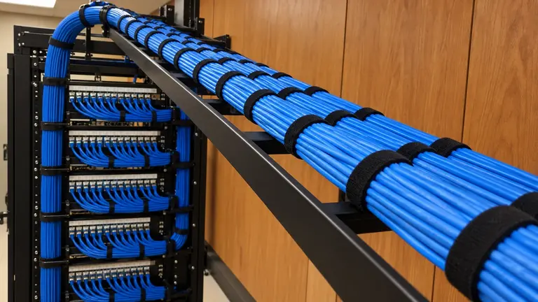
Unsupported equipment, blocked ventilation, poor patching, and undocumented power paths make maintenance and expansion risky.
Allocate access ports, uplinks, management interfaces, and growth capacity by device group and telecom location.
Compare connected-device power requirements and startup behavior with per-port and total switch budgets.
Arrange active equipment, patching, UPS dependencies, cable management, and service clearance in MDF and IDF spaces.
Define copper or fiber uplinks between switches and rooms according to distance, bandwidth, redundancy objectives, and available media.
Document proposed device groups, required communications, addressing inputs, and IT approval points for VLAN or policy implementation.
Provide the switching, cabling, PoE, uplink, and management foundation needed for separately designed wireless coverage.
Add cameras and access devices without exhausting edge-switch power or choking the route to recording and management systems.
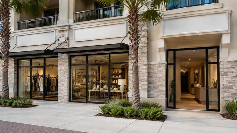
Separate landlord, tenant, security, and shared-service responsibilities before changing rack or VLAN assignments.
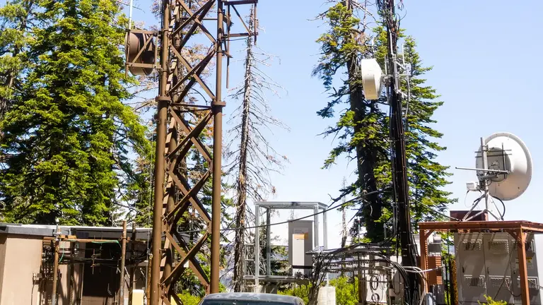
Connect a secondary switch through fiber or a planned outdoor link rather than treating the distant structure as an ordinary access-layer extension.
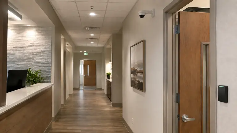
Schedule network changes around occupied operations and preserve the responsible IT team’s addressing and security controls.
Count endpoints, identify bandwidth and PoE needs, and map where management or recording services reside.
Document switches, rooms, backbone media, single points of failure, and distance between equipment locations.
Identify who approves IP addressing, VLANs, firewall rules, remote access, firmware, and administrative credentials.
Plan maintenance windows, temporary service, rollback conditions, connectivity tests, and post-change records.
Camera streams, access events, intercom sessions, and wireless clients have different traffic and availability needs. Network planning documents how they connect while each application retains its own placement, configuration, and operational acceptance criteria.
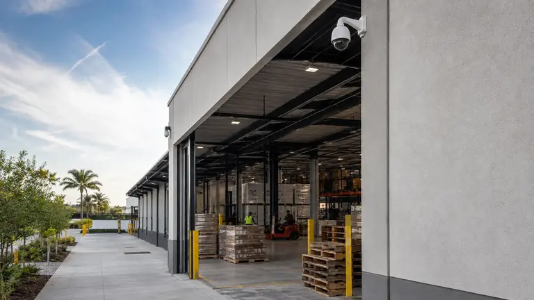
Warehouses, managed properties, professional offices, industrial sites, and large equestrian facilities may place equipment in several rooms or buildings. The network design should make those boundaries, backbone paths, and service responsibilities obvious to the people who will operate them.
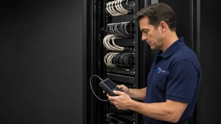
Provide tested passive links from endpoints to the active network.
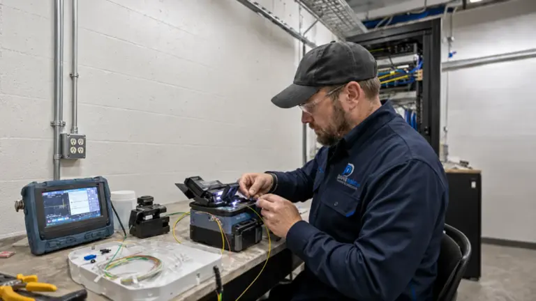
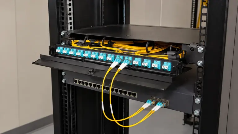
Build long-distance or building-to-building optical uplinks between telecom locations.
Evaluate outdoor bridge connectivity when a physical pathway is impractical and the RF path is suitable.
IT contacts, facility teams, property managers, contractors, and system owners use this service to coordinate active connectivity; it does not replace managed IT or application-specific system design.
Record current and planned ports, power needs, traffic, ownership, and management platforms.
Trace switches, uplinks, racks, telecom rooms, and backbone media.
Prepare configurations, approvals, cutover sequence, rollback criteria, and access windows.
Confirm negotiated links, PoE delivery, approved segmentation behavior, uplink performance, and updated documentation.
Ocala Security Cameras by Data Pro Communications is operated by Data Pro Communications for the Ocala Branch. Contact information: 603 E Fort King St, Ocala, FL 34471; (352) 517-4404; info@dataprocommunications.com. FL License #EC13016138.
Questions and answers
The scope can include switches, PoE, racks, uplinks, equipment-room organization, segmentation coordination, wireless readiness, connected-system capacity, cutover planning, and documentation.
Structured cabling creates tested passive links. Network infrastructure supplies and organizes the active equipment and logical connectivity that use those links.
Planning compares each device’s power class and expected draw, startup behavior, port assignment, switch limits, power-supply configuration, and growth allowance. Open ports alone do not prove sufficient PoE capacity.
The organization responsible for the network should approve VLANs, IP ranges, routing, firewall rules, permitted services, and administration. The project can document device requirements and proposed separation.
Fiber is evaluated for longer distances, higher backbone capacity, building-to-building routes, electrical separation, interference conditions, or a planned optical architecture. Optics and strand design must match both endpoints.
It can provide switch ports, PoE, cabling, uplinks, and controller or management readiness. Access-point placement and RF coverage require a separate wireless design based on the space and client needs.
Possibly, if port speed, PoE, uplink interfaces, software support, configuration access, rack conditions, and device compatibility remain suitable. The review should also consider the consequence of failure.
Identify each building and telecom room, backbone medium, distance, switch inventory, power, grounding responsibilities, required capacity, network ownership, and whether a physical pathway or outdoor wireless path exists.
No. Help desk, endpoint management, cloud administration, backups, cybersecurity monitoring, user support, and ongoing IT operations are separate unless specifically contracted under another scope.
Validation may include link negotiation, port assignment, PoE delivery, approved IP and VLAN behavior, uplink connectivity, access to required services, device reachability, and documentation of the final configuration.
Request a review of switches, PoE, racks, uplinks, segmentation inputs, and remote equipment locations.