
Backbone-first planning
Fiber type, strand count, route, enclosure, termination, optics, and test expectations are decided as one link.
Commercial Technology Solutions | Ocala and Marion County
Fiber provides a physical optical backbone for distances and building relationships that ordinary copper links may not support well. It can connect warehouses to offices, main buildings to barns, remote telecom rooms, industrial structures, and other separated facilities through a planned pathway and tested end-to-end link.
The backbone should be designed as an end-to-end optical link, not a spool of cable. Matching fiber, route, enclosures, connectors, optics, strand allocation, and test criteria protects the value of the difficult building-to-building work.
Fiber type, strand count, route, enclosure, termination, optics, and test expectations are decided as one link.
Long outdoor and building-to-building paths are evaluated without stretching copper beyond its practical application.
Identifiers, loss results, strand records, and endpoint documentation support later moves and troubleshooting.
FL License #EC13016138 is used as the approved factual credential for the branch.
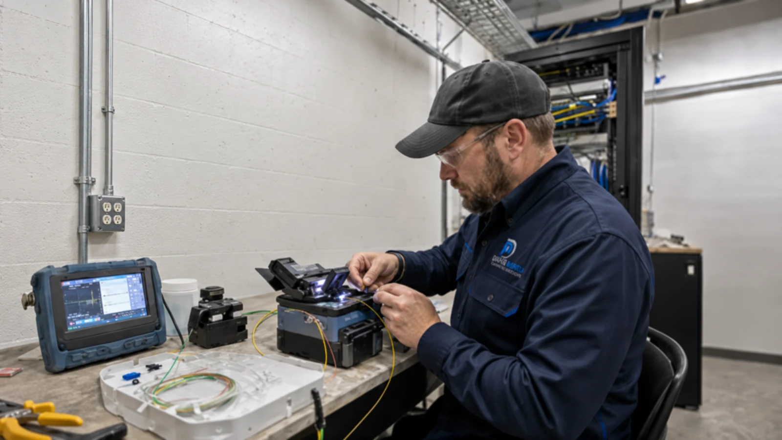
A useful fiber scope starts at the active equipment on each end and works through optics, connectors, fiber type, strand allocation, pathway, environmental protection, slack, enclosures, splicing or termination, and testing. Treating the cable alone as the system leaves critical compatibility decisions unresolved.
Conduit may be blocked, damaged, shared, undersized, flooded, or missing pull access along an outdoor route.
Switches, transceivers, connector types, fiber type, wavelength, and link speed must agree at both ends.
Outdoor entries, handholes, enclosures, bend control, pulling tension, slack storage, and restoration access affect long-term support.
Unidentified strands and missing loss baselines make later expansion and fault isolation unnecessarily difficult.
Create optical uplinks between offices, warehouses, barns, shops, clinics, equipment buildings, or other separated structures.
Connect multiple telecom locations through a documented backbone topology designed for current and future systems.
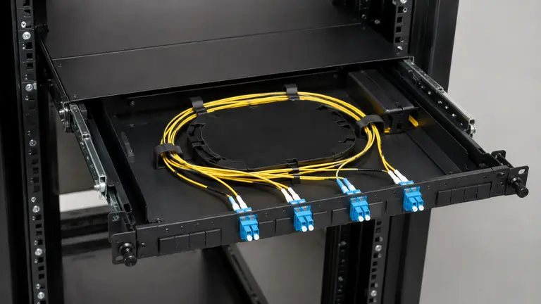
Use suitable enclosures, adapters, connectors, pigtails, splice trays, and strain relief for the selected fiber system.
Plan conduit, handholes, entrances, pull points, protection, and route access around the site conditions.
Match transceivers or media interfaces to fiber type, connector, wavelength, speed, distance, and switch support.
Record continuity, polarity, identifiers, and the agreed optical test results for each commissioned strand.
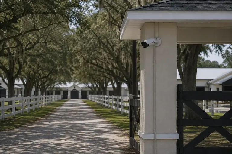
Carry network and camera traffic across a large equestrian property without placing a long copper channel between detached structures.
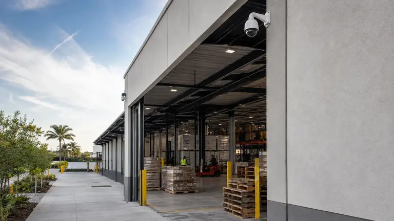
Provide an uplink between operational areas that need shared network services but occupy separate buildings.
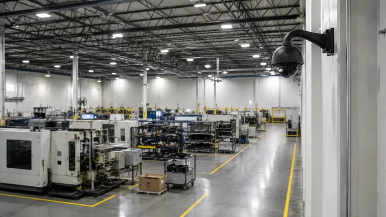
Extend the backbone to equipment serving yard cameras, access devices, or production spaces.
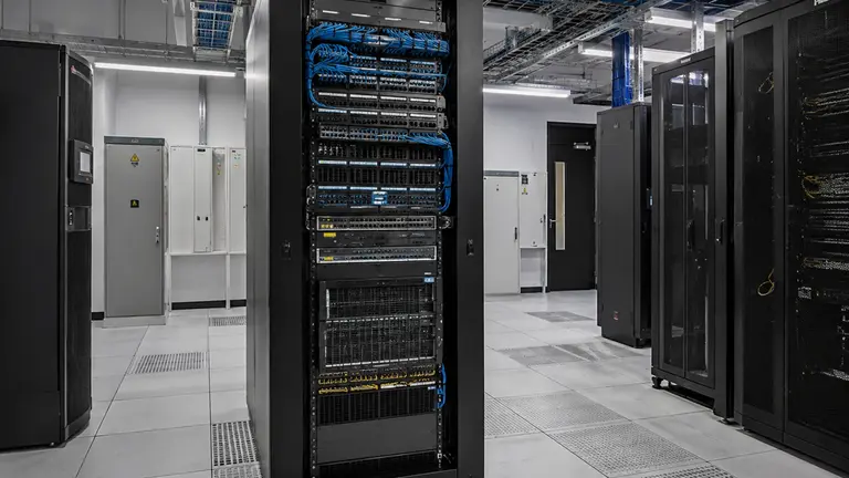
Install and document spare strands when the pathway cost and future site plan justify capacity beyond the first active pair.
Identify switches, speeds, optics support, traffic, redundancy objectives, and future strand needs at both ends.
Verify conduit, handholes, building entrances, distance, pull access, environmental exposure, and restoration constraints.
Choose fiber type, count, construction, connectors, enclosures, splice/termination method, and compatible optics.
Define loss-testing method, reference values, polarity, labels, strand map, and as-built route documentation.
A single optical route may support network uplinks used by cameras, access control, intercom, wireless access, and business connectivity. The connected systems still require their own bandwidth, segmentation, power, and operational designs at each endpoint.
Warehouses, industrial campuses, managed properties, and equestrian facilities often place useful technology beyond the main building. Where a physical route is available, fiber can create a durable backbone between structures while keeping remote switches and system endpoints within a documented topology.
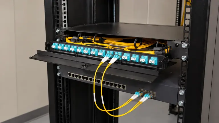
Supply the switches, uplinks, segmentation, and active capacity that use the fiber backbone.
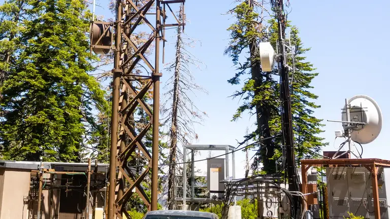
Evaluate a wireless bridge when a physical pathway is impractical and the outdoor path can support the requirement.
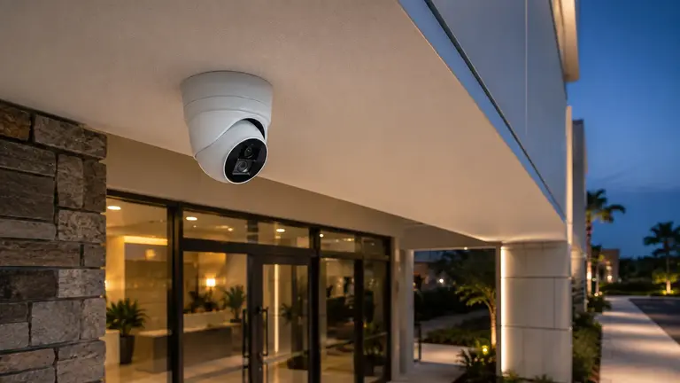
Plan cameras and recording that may use the optical route to reach remote buildings or yards.
Facility teams, network owners, contractors, industrial operators, and equestrian property managers use fiber to connect distributed telecom locations; detailed industry operating guidance remains separate.
Confirm equipment rooms, active interfaces, required capacity, and expected growth.
Inspect pathway continuity, length, entrances, pull points, and environmental conditions.
Place the selected cable, manage slack and enclosures, complete splices or connectors, and protect the route.
Verify polarity and optical performance, then deliver labels, strand maps, results, and as-built changes.
Ocala Security Cameras by Data Pro Communications is operated by Data Pro Communications for the Ocala Branch. Contact information: 603 E Fort King St, Ocala, FL 34471; (352) 517-4404; info@dataprocommunications.com. FL License #EC13016138.
Questions and answers
Fiber supports long links, high backbone capacity, and electrical isolation between structures. The route, equipment, fiber type, optics, and protection still require project-specific design.
Yes, when the pathway, endpoints, environmental protection, telecom space, power, and active equipment can support the link. The backbone may carry cameras, access, wireless, or business network traffic.
Distance, bandwidth, installed standards, available optics, connector strategy, future growth, and compatibility at both endpoints guide the decision. The choice should be made for the complete link, not from cable price alone.
No. The route must be checked for continuity, pull access, bends, fill, water, damage, entry points, handholes, and restoration constraints. A pull string by itself does not prove suitability.
Depending on scope, records may include strand identifiers, polarity, continuity, insertion-loss results, test direction, wavelengths, reference method, equipment used, endpoint labels, and notes on splices or events.
The count depends on active links, redundancy plans, topology, spare capacity, future buildings, pathway cost, and the owner’s standard. Spare strands should be intentional and documented.
They can be alternatives or, in some designs, different primary and backup paths. Fiber depends on a physical route; wireless depends on a suitable outdoor RF path, mounting, power, and interference conditions.
The scope must assign responsibility and confirm switch support, speed, wavelength, fiber type, connector, distance, and any vendor-specific requirements before procurement.
Possibly. The fault location, cable construction, available slack, route access, enclosure condition, strand availability, and test results determine whether repair, resplicing, strand reassignment, or replacement is reasonable.
Identify the buildings, approximate route, existing conduit or poles, telecom rooms, switches, required services, desired capacity, construction schedule, and any known pathway or excavation restrictions.
Request a review of endpoints, distance, pathway, fiber type, termination, optics, testing, and records.