
Count Devices by Space
Offices, cameras, access devices, phones and wireless access points are forecast by location before cable quantities are finalized.
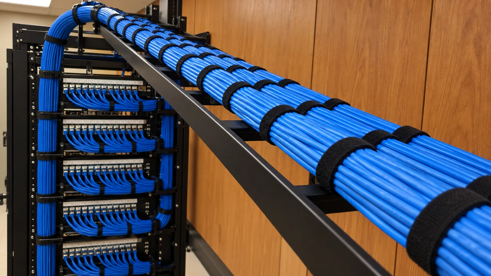
COMMERCIAL EXPANSION GUIDE
Cabling expansion should begin with the devices and work areas the property must support, then trace how each new connection reaches a serviceable telecommunications space.
Pathway access, cable counts, distance, rack capacity, backbone links, labeling and test records should be decided while walls, ceilings and construction schedules can still accommodate them.
Project planning principles
Offices, cameras, access devices, phones and wireless access points are forecast by location before cable quantities are finalized.
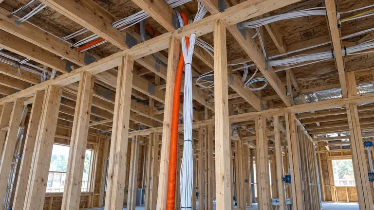
Ceiling access, sleeves, conduit and cable-support routes are reviewed while construction decisions can still change them.
Rack units, patch-panel ports, switch capacity and copper distance are checked before new runs are assigned to an existing room.
Permanent links are labeled and tested to the agreed category and handoff requirement, producing records that support troubleshooting and acceptance.
Spare pathway, backbone and rack capacity are recorded so later phases do not depend on assumptions about what remains available.
An expansion may add desks, cameras, doors, wireless access points, phones, printers and building systems at the same time. Each device needs a planned location, pathway and termination point, but it may not need the same cable type, outlet arrangement or activation date.
Start with the space plan and system schedule, then determine whether the current rack and backbone can absorb the growth. If a new IDF is required, its location should be selected for distance, serviceability, power coordination, cooling and a dependable uplink rather than whatever closet remains unassigned.
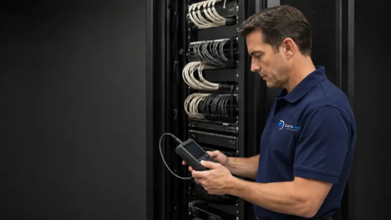
Count planned endpoints by room and system, including spare or future outlets that have a credible use. Distinguish installed cable from electronics that will be activated in a later phase.
Use the current reflected ceiling and furniture plans.
Include cameras, access, wireless and voice devices.
Name outlets that need special mounting or environmental treatment.
Verify tray, J-hooks, conduit, sleeves, penetrations and above-ceiling conditions. A route shown on a drawing may be blocked by structure, rated assemblies or inaccessible finished areas.
Review available rack units, patch-panel positions, cable entry, grounding and bonding scope where applicable, switch ports, power coordination and service clearance before assigning more drops.
Copper horizontal cabling has practical standards-based limits, so a distant addition may need a new distribution point with a fiber backbone. Measure the installed route, not the straight-line floor-plan distance.
Coordinate rough-in, ceiling closure, painting, furniture, device installation and testing. Protect installed cable and leave clear responsibility for temporary conditions or later activation.
Agree on naming before termination. Test completed links using the specified method, correct failures and hand off results with drawings and port records that match the installed work.
An established professional building may have limited ceiling access and an equipment room that has accumulated years of changes. A warehouse addition may offer open structure but place new work areas too far from the existing rack. Both require field verification before a drawing becomes a cable count.
Growing commercial and equestrian properties may also add detached offices, shops or arenas. Those additions should be treated as new distribution zones with a backbone decision, not as an opportunity to stretch horizontal copper beyond a practical route.
Furniture and wall changes move outlet locations while the existing rack remains. The team checks pathway access and old cable condition before deciding which links can be retained or removed.
The new area adds workstations, wireless coverage and cameras. Route length and lift access drive whether endpoints return to the main IDF or a new distribution point is justified.
A fiber uplink connects the new building to a small local rack, keeping copper runs within the addition and creating a documented boundary between backbone and horizontal links.
Pathways and labeled cable are installed during open construction, while selected electronics activate later. The handoff distinguishes tested links from live services.
Reserve panel positions, switch ports and rack units for the defined phase, then show the remaining capacity rather than describing it as 'plenty.'
Resolve sleeves, rated pathways, supports and difficult penetrations while the responsible trades can still reach them.
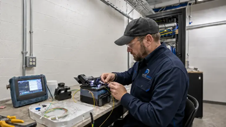
State whether verification or certification is required, the link configuration, naming format and the electronic result files expected at handoff.
Identify what remains in use, what is removed and what is reserved, following applicable project and code requirements.
Advantages
Spare pathways and rack positions reduce disruption for known growth.
Fiber backbones can support distant distribution points and additional capacity.
Consistent labeling shortens activation and troubleshooting work.
Electronic test records establish an acceptance baseline.
Limitations and Conditions
Unused cable and hardware still consume pathway, rack and budget.
Future device requirements can change beyond current assumptions.
Existing drawings may not match concealed pathways.
A new IDF introduces power, environment, access and uplink responsibilities.
Cameras, doors, wireless access points, phones and printers can add as many links as user workstations.
Empty rack units do not prove there are patch-panel positions, switch ports, power capacity, cooling or usable cable entry.
Real routes rise, turn, cross corridors and avoid obstacles. The installed pathway determines link length.
Results are less useful when the test identifier cannot be matched to the faceplate, patch panel and drawing.
Spare conduit or fiber is only helpful when its location, size, strand count, endpoints and current use are documented.
Use the latest architectural, furniture, reflected ceiling, security and technology plans, then reconcile them with field conditions.
Align rough-in and cable installation with demolition, framing, ceiling work, inspections and safe access.
Confirm rack layout, cable entry, service clearance, ventilation and authorized access for every distribution point.
Review fiber strands, uplink equipment and the network design needed to connect a new IDF or building.
Define label format, test standard, result files, as-built drawings and exception handling before installation begins.
Count endpoints by room and system.
Mark special mounting and environmental needs.
Survey ceiling, conduit, sleeves and cable supports.
Measure routes to existing racks.
Budget rack units, panels, ports and backbone capacity.
Decide whether a new IDF is required.
Coordinate rough-in and testing with construction milestones.
Define labels, electronic results and as-built records.
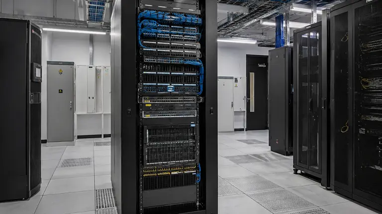
Data Pro provides commercial copper and fiber cabling for new work areas, network devices, cameras, access systems and building-to-building connections.
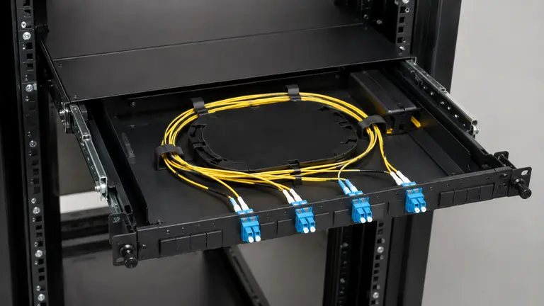
Continue with rack units, service clearance, power, ventilation and documentation for a new or expanded telecom space.
Coordinate switching, addressing and network capacity with the physical cabling plan.
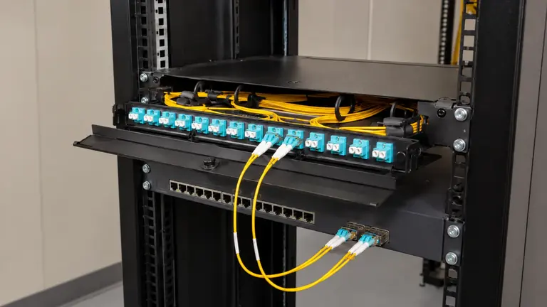
A new IDF, detached building or higher-capacity backbone may place fiber within the expansion scope.
Review the industry context for technology coordination within commercial construction schedules.
Coordinate the space plan with IT, security, facilities and operational device requirements.
Verify pathways, distance, rack capacity and the need for a new telecom space or backbone.
Sequence supports, sleeves, cable, termination and device work around construction access.
Correct failed links, reconcile as-builts and deliver records that identify every accepted connection.
Questions and answers
Plan it while floor plans, ceilings, walls and equipment spaces can still change. Early coordination helps reserve pathways, sleeves, rack capacity and backbone routes before construction closes access.
Count endpoints by room and system, including workstations, phones, wireless access points, cameras, access devices and other networked equipment. Add future capacity only where a credible use and termination plan are defined.
Review available rack units, patch-panel positions, cable entry, switch ports, power coordination, cooling and service clearance. Empty space alone does not prove the rack can support the expansion.
A new IDF may be appropriate when horizontal cable routes would be too long, the endpoint count is substantial or a new floor or building needs local distribution. It also requires an uplink, secure access and suitable environmental conditions.
Fiber can connect a new IDF or detached building over longer distances and provide backbone capacity. The design should define strand count, pathway, termination, test method, equipment and documented spare capacity.
Reuse may be practical when the cable type, route, labels, condition and test results support the new application. Unidentified or inaccessible links should not be counted as usable capacity without verification.
It evaluates the fixed installed portion of a balanced copper link without the user patch cords. The specified test method and limits should match the cabling category and project acceptance requirement.
Request outlet and panel labels, electronic test results, as-built locations, patch-panel assignments, backbone records and documented exceptions. The names should match across the faceplate, rack and drawings.
Separate the installed-and-tested link scope from later electronics activation. Protect cable ends, label reserved connections and document which outlets are accepted, active or held for a defined future phase.
Identify reserved pathways, conduits, fiber strands, patch-panel positions and rack units on the as-built records. Mark what is installed and tested, what is available but inactive and which future spaces or systems the capacity is intended to support.
Bring the endpoint forecast, telecom-room information and construction milestones to a coordinated review with the owner, IT team and project partners before pathways close.